
If you’ve ever had a damaged RJ45 connection on your security camera, then you know just how frustrating this can be. Not only is your security camera unusable, but your warranty is voided. But hold on! Before you give up on your camera, there is a quick fix that could get your camera back up and running. Here’s how to fix your security camera’s damaged cable connection step-by-step.
Method 1: Use an Ethernet Coupler
- Cut off the damaged connector
- Crimp an RJ45 connector onto your camera’s cable
- Use an Ethernet coupler and cable to connect the camera to your network
- Test it out to see if your camera is working
Method 2: Use a Keystone Jack
- Cut off the damaged connector
- Punchdown your cable into a keystone jack
- Use an Ethernet cable to connect the camera to your network
- Test it out to see if your camera is working
Quick Disclaimer
Depending on the type of damage and the amount of damage done to your connector, these fixes may or may not work. For instance, if you got rain inside your connector, there’s a good chance it already fried your camera. But if the damage is confined only to the connector, then this fix should get you back up and running in no time. If you’re not sure how far the damage has spread, it’s still worth a shot. I mean, the alternative is throwing away your camera.
So with that said, let’s jump into it! There are two ways you can do this, depending on what tools you have at your disposal. If you're starting from scratch, we recommend starting with Method Two. All tools for either method can be purchased right from Nelly's Security.
Method 1: Use an Ethernet Coupler
Our first method is going to involve using an Ethernet coupler to create a makeshift pigtail for your camera. For this, we'll need a few tools.
Tools You Need For Fixing Your Security Camera’s Pigtail
For this project, you need four things:

- A camera with a damaged RJ45 connection
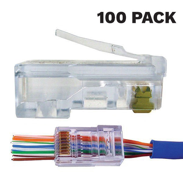
- An RJ45 pass-through connector
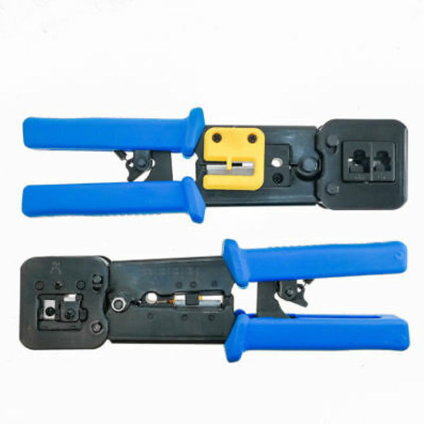
- An RJ45 crimp tool
- An Ethernet coupler
You can pick up all of these tools (minus the damaged camera) on our website. Just click the links above if you need anything. Don’t worry about buying a full pack of couplers or connectors just for this one project. First, it may take you a couple of tries to get it right, so it’s always good to have extra connectors. But also, these are just good supplies to have on hand anyway. You never know when you’re going to need to terminate an Ethernet cable or fix a damaged security camera.
Step One: Cut Off the Damaged Connector
Now that you have your supplies, it’s time to get to work. Using your crimp tool or a pair of wire cutters, cut off the damaged connector. You can actually cut off the whole pigtail if you don’t need the other connections.
Now take your crimp tool and strip back your camera’s cable jacket. You’ll probably find some insulation in there, but you can just pull that back to reveal the colored wires inside. You can also cut off that insulation just to make sure it’s out of the way.

Step Two: Terminate Your Cable
Next we’re going to terminate our camera’s cable, which just means we’re going to crimp our RJ45 connector onto the end of it. This is going to look a little different depending on your camera.
Terminating an R-Series Cable
We'll start with R-Series cameras, which are a bit trickier than the rest, simply because it doesn’t have a full set of wires. When you cut open your cable and strip back the jacket, you’ll see a total of eight cables: orange, orange and white, green, and green and white. These are familiar. But then there’s red, red and white, black, and black and white.
Go ahead and cut off the solid red and the solid black; these are from the 12V DC connector, so if you're using Power over Ethernet, you don’t need them. If you're not using Power over Ethernet, go ahead and cut these wires off and get yourself a PoE switch. You'll thank me later. I suppose you could also wire these two cables to a 12V DC power supply, but why make things more difficult on yourself than necessary?
Once we cut those off, we’re left with six wires. Which means we’re going to have to be very careful about how we terminate this cable.
If you take a close look at your RJ45 pass-through connector, you’ll see eight tiny little rivets. These rivets are used to guide your wires into the eight pins. But since we don’t have eight wires, we’re going to have to skip some of these rivets.
We’re going to use the orange and green cables for our two data pairs. But instead of two energized pairs, we’re only going to use the red stripe and black stripe for power. The red stripe will be positive (in the place of the blue solid and blue stripe wires) and the black stripe will be negative (in the place of the brown stripe and brown solid wires).
So here’s the order we need:

It may take a bit of practice getting those wires in just the right place, but trust me. If I can do it, you can do it.
Once everything is in the right order, slide the pass-through connector over the cable and crimp it into place. Congrats! You can now move onto step three.
Terminating an H-Series Cable
If you have an H-Series camera, the process is going to be pretty straightforward. Once you strip your cable and pull back the insulation, you should see ten wires: the eight standard wires you find in an Ethernet cable (although these will be different colors) and the two wires from the 12V DC connection.
Again, take those two power wires (the red and the black) and cut them off.
Once those power wires are out of the way, you’re left with eight colored wires. If you’re used to terminating Ethernet connections, then this might look a little scary, because these aren’t the eight colors that you’re used to. That’s okay! We’ll help you line these up in the correct order.
The standard eight colors are orange, orange and white, green, green and white, blue, blue and white, brown, and brown and white. In a standard Ethernet cable, the two orange wires and the two green wires are used for data, while the blue and brown wires are used for PoE.
Inside your H-Series connection, you will have wires with these colors: white, brown, blue, gray, purple, green, yellow, and orange.
Get these in the correct order:

Slide the RJ45 connector over your cable and crimp it down. Congrats! You can now move onto step three.
Terminating a Uniview Cable
Uniview is going to be the simplest out of the three cameras. That's because the pinout diagram for Uniview is identical to the T-568B Ethernet wiring. So to get your Uniview camera terminated, you're going to line the colors up exactly the same way you would line them up for a standard Ethernet cable: orange stripe, orange, green stripe, blue, blue stripe, green, brown stripe, and brown.

Additional Cable Types
Depending on your camera, you may find different wires inside your cable. For instance, if your camera’s pigtail had audio connections, alarm connections, BNC connections, or anything else, you’ll obviously have more wires to deal with in your cable. But knowing how to handle the two types of pigtails above, you should be able to navigate your way through any other type of camera you come across. Just be careful to pay close attention to your camera’s pinout diagram.
Method Two: Using a Keystone Jack and Punchdown Tool
This method is the easiest to do, as long as you have a keystone jack and punchdown tool handy. Here are the tools you need for this method:
Tools You Need For Fixing Your Security Camera’s Pigtail
For this project, you'll need four things:

- A camera with a damaged Ethernet connection
- A keystone jack (available in two types: those that need a tool and those that don't)
- A punchdown tool (not required if you have a tool-free keystone jack)
- A Cat5 cable stripper
Once again, you can pick up all of these tools on our website by clicking the links above. Again, these are always great tools to have laying around just in case you find yourseelf in a situation like this.
Step One: Cut Off the Damaged Connector
Just snip it right off with a pair of wire cutters. Again, you can go ahead and cut off the whole end of the pigtail if you don't need the other connections.
Step Two: Line Up Your Wires
With this method, we won't be crimping an RJ45 connection onto your Ethernet cable. Instead, we'll be punching your Ethernet cable down into the keystone jack. There are a couple of ways you can do this, depending on the type of keystone jack you have at your disposal. We have some that require tools and some that don't.
Regardless of which kind of keystone jack you'll use, the important thing here is to get the cables lined up in the correct order based on the on the guide printed on your keystone jack. You'll most likely have a color code alongside a number, with two standards: T-568A and T-568B. It's important that you pay closer attention to the number than the color, especially if you have an H-Series or an R-Series camera. If you have a Uniview camera, you can follow the color code, as the Uniview's wire colors will line up. However you decide to line up your wires, be sure you're following the T-568B standard here.
For most keystone jacks, you'll go in this order: Left Side, Top to Bottom: 2, 1, 6, 3; Right Side, Top to Bottom: 4, 5, 7, 8 . However, if your keystone jack does not require a tool, you may be inserting your cable into the jack upside-down. In that case, you'll be punching down your cable in this order: Left Side, Top to Bottom: 4, 5, 7, 8; Right Side, Top to Bottom: 2, 1, 6, 3. Again, just follow along with the B standard diagram on your keystone jack to ensure your cables are placed in the proper order.
Diagram for Standard RJ45 Keystone Jacks

Diagram for Toolless RJ45 Keystone Jacks

Step Three: Punch Down Your Wires
If your keystone jack requires a punch down tool, you can do each wire separately. Using the tool, simply push down on the wire to embed it into the jack's terminal. Makd sure the punchdown tool's blade is positioned on the outside of the jack, so that it can cut away any excess wire. You may have to punch down a couple of times to cut the wire properly.
If your keystone jack does not require a tool, you'll need to line up each wire at the same time. Then you'll snap your jack closed. Sometimes your jack will include a small lever ,which you can use clamp the jack even tighter to aid in cutting off any excess wire.
Finishing Up
Regardless of which of the two methods you used to fix your connection, you are now done. You now have a makeshift RJ45 Ethernet connection made out of either an Ethernet coupler or an RJ45 jack. All you need to do now is connect your Ethernet coupler to the camera, and you now have a security camera with your very own make-shift pigtail. Connect that bad boy to your network and see if she fires up.

If your camera turns on and shows up on your network, congratulations. You have successfully brought your camera back from the dead. If your camera turns on but doesn’t show up on your network, double-check that you have all the wires in the correct order. If your camera isn’t turning on at all, then the damage may not have been confined to the connection and your camera may be done for.
If your camera is working again, you may need to weatherproof that connection before you install it outside. To do that, just pick up some weatherproof tape and go to town. Make sure everything is fully covered. It’s not going to look pretty, but I never said this fix would be aesthetically pleasing.
Your Turn
Did this fix worked for you? Do you have any other tips for dealing with a damaged security camera? Share it with us in the comments below! It just might help out someone else. If you run into any issues during this process and have questions, don’t hesitate to give us a shout. We’re always here to help.